|
|
|
|
|
|
Tutorials |
|
Using UV Sets and Layered TexturesPage 1 |
|
|
The goal of using UV sets is to have different UV
projections with different textures on the same object. For example, let's
say that you have a building that you want to map with a brick
texture. You also want to put some dirt in certain places. You want the
brick texture to tile and cover the whole building, but not the dirt. Let's see how to do this with UV
sets and layered textures with the help of a simple cube. |
|
|
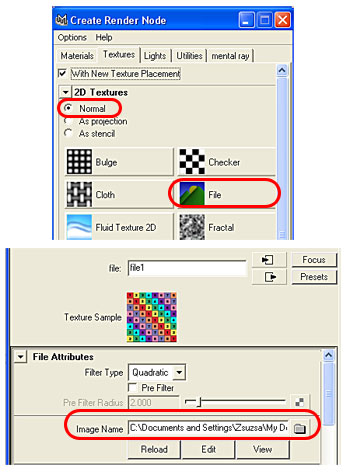
1. Create a polygon cube in your scene, scale it and position it as you like. I scaled mine 10 in x, 10 in y and 15 in z. 2. Put some lights in the scene. 3. Select the cube and assign a new material to it. (Right-click the cube, then go down to Materials / Assign New Material and choose a material - I picked a lambert). 4. Let's make a simple UV map for the cube. We are not going to make a new UV set for this UV map yet; this base map is going to use the default UV set (map1). If you are familiar with UV mapping, then go ahead and make a UV map for your cube, then go on to step #16 on page 2. If you need help with the UV mapping, then read on. 5. First, let's assign a UV mapping texture to the cube to help with the UV mapping. Checker textures are good for this purpose, and if the texture has different colors and numbers, it's even better. If you have a texture like this, use that, or you can download mine here. 6. With the cube selected, go to the Attribute Editor, and in the material tab click on the checker box by the Color node, then click on File to create a texture node. (Be sure that you are in Normal mode at the top of the Create Render Node window.) Load the UV mapping texture file. See Figure 1.
|
|
Figure 1 |
|
|
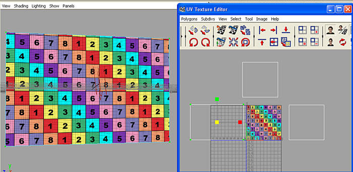
7. Middle-click inside the Perspective View window to activate it, then hit 6 on your keyboard to get into textured shading mode. Now you can see the file texture on your cube. If you examine the cube from all sides, you can see that the texture is tiled on the surface of the cube, but it's sideways and upside down in some places. This is because of the cube's default mapping. Select the cube, then open up the UV Texture Editor (Window / UV Texture Editor). If you zoom out, you can see the default map. The map goes outside of the 0 to 1 UV space, which makes the texture tile across the surface. If you go to Image / UV sets, you can see that the cube has one UV set: map1. (Fig. 2) 8. Let's make our own UV map. Move the UV Texture Editor to the side so you can see the cube. Hit the Spacebar on your keyboard to bring up the 4 panel view, get into face selection mode, then, in the front view, select the cube's front and back faces by drawing a rectangle around the dot in the middle. Now go to Polygon UVs / Planar Mapping -- options box. Since the front and back faces are positioned along the Z axis, select Z axis for the mapping direction, then click Project. See Figure 2.
|
|
|
|
|
Figure 2 |
|
|
9. You should see the UV manipulator both in the view panels and
inside the UV Texture Editor. In the UV Texture Editor click on
the circle in the middle of the manipulator, then move the UVs to another
quadrant, out of the 0-1 space. The reason for doing this is so that
later the UVs of the different areas will be well separated and it will be
easier to select them and move them around. (If you have some display
problems and can't see the manipulator, then select the front and back
faces, CTRL-right click inside the UV Texture Editor and select "To
UV". Hit W on your keyboard and move the UVs.) See Figure 3.
|
|
|
|
|
Figure 3 |
|
|
10. Click on the cube and select the side faces in the side view. Now go to Polygon UVs / Planar Mapping - options box, and this time select X axis for the mapping direction. Click Project, then move the UVs to another quadrant. 11. Now select the top and bottom faces in top view, go to Polygon UVs / Planar Mapping - options box, and select Y axis for the mapping direction, then click Project. Move these UVs to yet another quadrant in the UV Texture Editor.
|
|
|
12. Put your cursor over the perspective view panel, then hit the
Spacebar on the keyboard to maximize the perspective view. Now we
need to adjust the UVs so that the UV mapping texture's checker pattern
will be nice and square everywhere and the numbers on the texture will
face the way we want them. Select the UVs of the side faces inside
the UV Texture Editor (right-click in the editor, choose UV, then select
the UVs, or select the side faces in the perspective view, then CTRL-right
click inside the UV Texture Editor and select To UV). Hit the
"r" key on
your keyboard to scale the UVs. Scale in the X axis by dragging on
the red handle until the checker pattern looks nice and square on the
cube. (See Figure 4.) For me the front and back faces are square, so I
don't have to worry about scaling the UVs now, but if yours are different,
then do these steps with those faces, too.
|
|
|
|
|
Figure 4 |
|
|
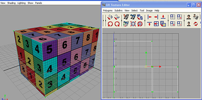
13. The top and bottom faces' UVs are rotated, so let's change that. Select the top and bottom faces, then, inside the UV Texture Editor, go to Polygons / Rotate UVs -- options box. Set the rotation angle to -90 degrees, then click Rotate. Now scale these UVs, too, until the texture on these faces look nice and square. Keep checking the perspective view while you're working in the UV Texture Editor and make sure that the sizes of the checkers are the same on all sides of the cube. This will ensure that the final texture will be uniform in size on the whole object. (If this object was a building, where you won't really see the top and bottom faces, you wouldn't have to worry about the mapping of those faces. However, if this was a cube in a scene where you would see all the faces, you would want to map the top and bottom faces carefully, too.) 14. Okay, so now the checker texture on the cube looks good, but if you look at the cube from all sides, you can see that the texture is flipped on the back, the bottom, and the left side. (This is where the numbers of the texture come in handy.) This happens because we projected the UVs in pairs (front and back; top and bottom, left and right sides), along the same axis. This would make the bump maps inverted. So, let's fix that. In the perspective view, select the back face (where the UV texture is flipped), then, inside the UV Texture Editor, go to Polygons / Flip UVs -- options box. Make sure that the Direction is Horizontal and the Coordinate is Local, then click Apply. Now the texture will be displayed correctly. Select the left side face and flip those UVs, too. Select the bottom face, but this time, before you flip the UVs, change the Direction to Vertical. 15. Now let's scale and position the UVs so that they will fit inside the 0 to 1 UV space. You might want to turn off the image display in the UV Texture Editor to make it easier to see things. To turn it off, go to Image / Display Image. Right-click in the Editor, then select UV, and select and position the UVs so that you have the top and bottom UVs on the top, and the front/back and side UVs side by side. Now select all the UVs, scale them and move them together until they all fit inside the 0 to 1 space. See Figure 5.
|
|
|
|
|
Figure 5 |
|
|
|
|
|
Copyright © 2002-2012 by Susan Lee. |
|


